Stella and Rose's Books Logo

Stella & Rose's Books

Specialists in Rare & Collectable Books

  Basket is empty
  Login Register

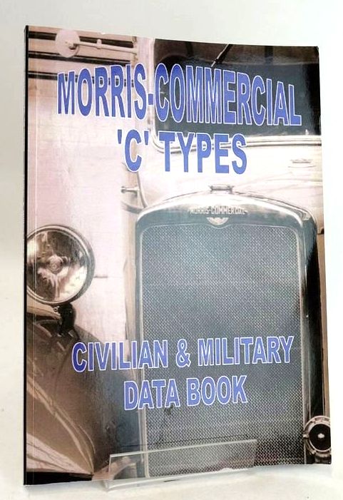
MORRIS COMMERCIAL 'C' TYPES CIVILIAN & MILITARY DATA BOOK

by Norman Painting

Published by Rossendale Books. 1st. 2015

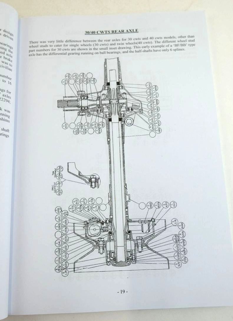
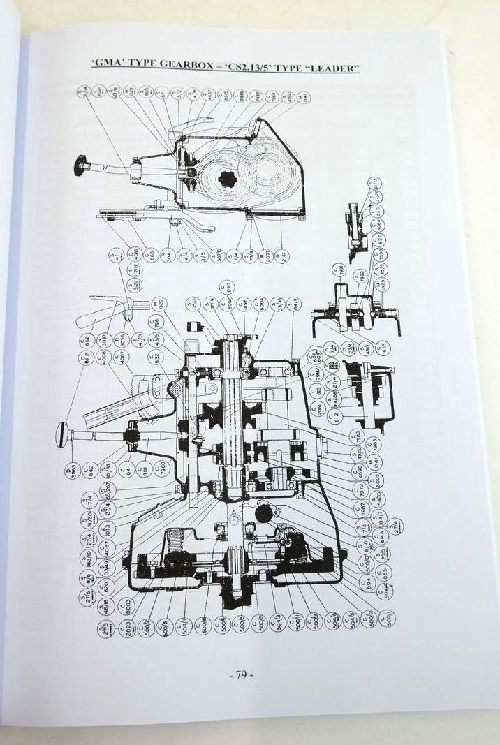
Slightly better than very good condition. The 'C' type vehicles were one of the most important ranges introduced by the Company, covering 30cwt to 5 tons for civilian vehicles and many variants for military applications. The technical data presented here is accompanied by sectioned drawings of all the major mechanical components, providing a useful reference work for these vehicles. Large format. Pictorial cardwraps. B/w photos and diagrams. 198 pages.

Crease to lower front corner of cover and a few pages in from front. Contents clean.

Stock no. 1831042

Enquire about this book Add to Wish List

Contents

  • CIVILIAN MODELS
  • General information about 'C' type civilian range
  • AXLE-FRONT
  • Technical Data and Modifications
  • '11/30', '11/40' type front axle
  • 1938 30/40 cwts type front axle drawing
  • 'C13/60F' type rear axle drawing
  • 'CS2.13/80' type front axle drawing
  • 'S2.10/5' & 'CS2.13/5' type front axle drawing
  • AXLE-REAR
  • General Data
  • 30/40 cwts early model rear axle drawing
  • 30/40 cwts late model rear axle drawing
  • '13/60F' type rear axle drawing
  • 'CS2.13/80' type rear axle drawing
  • '10/5' & '13/5' type rear axle drawing
  • BRAKE GEAR
  • 'CS11/30' type original brake gear layout
  • 'CS11/30' type modified brake gear layout
  • 'CS13/60F' type original brake gear layout
  • 'CS13/60F' type modified brake gear layout
  • 1938 'C11/30' type brake gear layout
  • 'CS2.10/5' "Leader" type brake gear layout
  • 'CS2.13/80' type "Leader" brake gear layout
  • 'CS2.13/5' type "Leader" brake gear layout
  • BRAKES
  • Technical Data concerning brake master cylinders, wheel cylinders, brake shoes and brake drums
  • Brake/clutch pedal gear for 30 cwts & 40 cwts normal control chassis
  • Brake/clutch pedal gear for '13/60F' type forward control chassis
  • Rear brake drawings for 30/40 cwts & '13/60F' types
  • Rear brake drawing for 'CS2.13/80' type
  • Rear brake drawing for '10/5' & '13/5' types
  • CARBURETTORS
  • General Data for all 'C' type carburettors
  • Information about petrol tanks and Autovac
  • Sectioned drawing of Solex 30 BFGV type "Self-Starter" carburettor
  • Sectioned drawings of Solex 30 MOVL type "Strangler" carburettor
  • Sectioned drawings of Solex 35/40 type "Thermostarter" carburettor
  • CHASSIS FRAMES
  • Chassis Frame Dimensional Data and Modifications
  • Chassis frame drawings for 1934 'CS11/30, 'CS11/40' and 'CS13.40' types
  • Chassis frame drawings for 'CS11/30F' and 'C11/30F' types
  • Chassis frame drawing for 'CS13/60F' type and 'C9/s80' types
  • Chassis frame drawing for 'CS2.13/80' type
  • Chassis frame drawings for 'SC2.10/5' and 'CS2.13/5' types
  • CONTROLS
  • Drawings of Steering column controls as fitted to non "Leader" models
  • Drawings of carburettor controls for normal control 'C' type models
  • Drawings of carburettor controls for forward control 'C'' type models
  • Drawings of carburettor controls for "Leader" models
  • CLUTCH
  • Drawings of clutches and pedal adjustment
  • ENGINES
  • General description of 'C' type engines
  • Technical data for 'OC', 'OF', and 'ON' ee6 cylinder engines
  • Technical data for 'OM' eeeee6 cylinder, and 'EA' & EC' 4 cylinder engines
  • 4 cylinder engine modifications
  • 6 cylinder engine modifications
  • Drawings of 4 cylinder engine lubrication system
  • Drawings of 4 cylinder engine timing chain, valve timing diagram, distributor and cylinder head
  • Drawings of 6 cylinder engine lubrication system
  • Drawings of 6 cylinder engine timing chain, valve timing diagram, distributor and cylinder head
  • Drawings of 'OM' type 6 cylinder head/valves and valve timing diagram
  • Part sectioned drawings of 1937 'EA' 4 cylinder engine
  • Part sectioned drawings of 1934 'OC; 6 cylinder engine
  • Part sectioned drawings of 1935 'OG' 6 cylinder engine
  • Part sectioned drawings of 1937 'OM' 6 cylinder engine
  • Illustrations of water pumps
  • GEARBOX
  • Gearbox Types, Ratios and Modifications
  • Sectioned drawing of 'GA' type gearbox
  • Sectioned drawing of 'GB; type gearbox
  • Sectioned drawing of 'GK' type gearbox
  • Sectioned drawing of 'GMA' type gearbox
  • PRODUCTION DATA
  • Information relating build dates of models with Sanction Numbers and Chassis numbers
  • RADIATORS
  • Chart giving data for radiators, mountings, and water hoses for 'C' type range
  • ROAD SPRINGS
  • Road Spring Data for 'C11/30', 'CS11/30', 'C11/30F', 'CS11/30F', 'C11/40'. 'CS11/40', 'C13/40', 'CS13/40F', 'CSs11.30' Ambulance, 'CS13/60F' types and 'CS2.10/5' and 'CS2.13/5' types
  • STEERING GEAR
  • General information about 'C' type steering gear with drawings of adjustable, and no-adjustable, ball joint assemblies
  • Drawings of '13/60F' type steering gear, and of late model steering wheel assembly with hub cover to hide steering wheel retaining nut
  • TRANSMISSION
  • General information about 'C' type and "Leader" type transmission, with sectioned drawing of 11'-2" wheelbase transmission layout
  • Sectioned drawing of '13/80' "Leader" type transmission layout, together with drawing of "Layrub Type" coupling used on "Leader" '13/5' type
  • TYRES
  • Tyre Data for whole of 'C' type range
  • WIRING DIAGRAMS
  • Wiring diagrams for early models fitted with 3 terminal type dynamo and "Trafficators", and wiring diagram for later models fitted with 2 terminal type dynamo
  • General information about 'C' type military vehicles
  • AXLES - FRONT
  • Technical Data
  • 'CS8' Mk.1 and early 'CDSW' type front axle drawing
  • 'CS8' Mk. 3 and 'C4' Mk.1 type front axle drawing
  • 'CW;, 'CD', 'CDF' & 'CDFW' type front axle drawing
  • 'CS9.LAC', 'CS10/80' some 'CDSW' types front axle
  • 'C8'' Mk.1 type front axle drawing
  • 'C8' Mk.3 type front axle drawing
  • AXLES - REAR
  • Technical Data
  • 'CS8' Mk.,1 & Mk.2 type rear axle drawing
  • 'CS8' Mk.3 type rear axle drawing
  • 'CD', 'CDF', 'CDFW' & 'CDSW' type rear axle drawing
  • 'C9' & 'C8' Mk.2 type rear axle drawing
  • 'C8'/GS Mk.3 type rear axle drawing
  • BRAKE GEAR LAYOUT
  • 'CS8' Mk.s1 type brake gear layout drawing
  • 'CS8; MNK.3 type brake gear layout drawing
  • 'CW11/30' type brake gear layout drawing
  • 'CD' type 6x4 brake gear layout drawing
  • 'CDF'/'CDFW' type 6x4 brake gear layout drawing
  • 'CS9.LAC' type brake gear layout drawing
  • 'C8' Mk.1 & Mk.2 4x4 brake gear layout drawing
  • 'C8' Mk.3 type 4x4brake gear layout drawing
  • BRAKES
  • Technical Data
  • 'CS8' type brake/clutch pedal arrangement drawing
  • 'CS8' type rear brake drawing
  • 'CD' & 'CDF'/'CDFW' & 'CDSW' type rear brake drawings
  • 'C8' type brake pedal arrangement drawing
  • CARBURETTORS
  • Model/carburettor chart
  • Carburettor specification chart
  • Solex 35 RFVDLOS type carburettor drawing
  • Solex RFVDL type carburettor drawing
  • Solex 35 BFDV type Carburettor drawing
  • Engine speed governor illustration
  • Fuel system data & Autovac illustration
  • DIMENSIONAL DATA
  • General dimensional chart for all models
  • CHASSIS FRAMES
  • Chassis frame dimensional data chart
  • 'CD' & 'CDFW' type chassis frame drawings
  • 'CS8' type chassis frame drawing
  • 'C8' type chassis frame drawing
  • CLUTCH
  • Clutch data and clutch drawings
  • CONTROLS - ENGINE
  • Early 'CW' & 'CS8' type steering column controls
  • DRIVING COMPARTMENTS
  • 'CS8', 'CD', 'CDSW', 'CDF' & 'CDFW' type illustrations
  • 'C8' & 'C9' type illustrations
  • ELECTRICAL EQUIPMENT
  • Chart of engine electrical equipment
  • Chart of lighting & electrical control equipment
  • Illustrations of screened ignition equipment
  • ENGINES
  • Model data and chart of model/engine types
  • Illustrations of 4 cylinder engine lubrication equipment
  • Illustrations of 4 cylinder engine valve timing, distributor an d cylinder head tightening sequence
  • 'EB' type 4 cylinder engine sectioned side view and end vies
  • 'EH' type 4 cylinder engine sectioned side view and end view
  • 'EHB' type 4 cylinder engine sectioned side view and end view
  • Illustration of 6 cylinder engine lubrication equipment
  • Illustrations of 6 cylinder valve timing, distributor and cylinder head tightening sequence
  • 'OH' type 6 cylinder engine sectioned side view and end view
  • 1940 'OH' type 6 cylinder engine sectioned side view and end vies
  • 'AX' type 6 cylinder engine sectuo9ned side view and end view
  • Illustrations showing lubrication system and engine valve timing for 6 cylinder 'AX' type engine
  • GEARBOXES
  • Gearbox types and ratios
  • 'CW', 'CS8' Mk1 & Mk.2 gearbox drawing
  • 'CS8' Mk.3 & 'C4' Mk.1 gearbox drawing
  • 'CS8' Mk.3 Compressor model gearbox drawing
  • 'CD' & 'CDF' type gearbox drawing
  • 'CDFW' & 'CDSW' type gearbox drawing
  • 'CDFW' & 'CDSW' type winch drive drawing
  • 'C8' Mk.1 & Mk.2 type gearbox drawing
  • 'C8' Mk.3 type gearbox drawing
  • 'C8'/'C9' type front wheel drive control drawings
  • 'CS9.LAC' type gearbox drawing
  • RADIATORS, MOUNTINGS & HOSES
  • Chart showing part numbers for all models
  • ROAD SPRINGS
  • 'CS8 Mk.1 & Mk.3, 'C4' Mk.1, 'CD', 'CDF', 'CDFW, 'CDSW' & 'C8' Mk.1, 'C8' Mk.3 & 'CS9.LAC'
  • Drawing showing Fulcrum Damper on 'CD', 'CDF', 'CDFW' & 'CDSW' types
  • STEERING
  • Steering type for all models. Drawings for 'CS8' Mk.1 & Mk.3, 'CD', 'CDF', 'CDFW' types & 'C8' Mk.3
  • TRANSMISSION
  • Drawings for 'C8' Mk.1 & Mk.3, 'C9/C8' Mk.1 & 'C8' Mk3
  • Drawing for 'CD', 'CDF', 'CDFW' & 'CDSW' types
  • TYRES
  • tyre and rim sizes for all models
  • WIRING DIAGRAMS
  • 'CS8' Earth Return & Double Pole wiring
  • 'CS8' Office and Wireless Truck wiring
  • Layout of 'CS8' Wireless Truck
  • 'CD' Earth Return and 'CDF'/'CDFW' Double Pole wiring
  • 'CDSW' Earth Return and 'C8' Earth Return wiring
  • BREAKDOWN LORRY
  • 'CDSW' type breakdown lorry equipment
  • CONTRACTS AWARDED 1935 - 1940

Similar Stock